Engineering and Technology
A high-performance capillary-fed electrolysis cell promises more cost-competitive renewable hydrogen
A. Hodges, A. L. Hoang, et al.
The study addresses the challenge that green hydrogen from water electrolysis is not yet cost-competitive with fossil fuels, primarily due to high operating energy consumption and significant balance-of-plant complexity. The research proposes and tests a capillary-fed electrolysis (CFE) architecture where a porous, hydrophilic separator wicks electrolyte via capillary action to the electrodes, enabling direct gas production in gas chambers with largely bubble-free operation. The hypothesis is that eliminating bubble formation at the electrodes and counterflow multiphase transport, while reducing ionic and contact resistances, will improve cell voltage-efficiency and simplify the balance-of-plant. The work situates itself in the context of advances from classic flooded alkaline to zero-gap and asymmetric PEM cells and aims to push efficiency beyond current commercial alkaline and PEM benchmarks and towards IRENA’s 2050 target for stack electrical efficiency.
The paper builds on prior understanding that gas bubbles at electrodes increase overpotentials and reduce effective catalytic area, degrading electrolysis efficiency. It references evolution of electrolyser architectures, including asymmetric PEM designs that directly produce one gas without bubbling, and prior demonstrations of bubble-free or substantially bubble-free electrocatalysis. NiFe oxyhydroxide is cited as a state-of-the-art OER catalyst in alkaline media, and Pt/C as a high-performance HER catalyst. The work contrasts gas crossover mechanisms in alkaline (diffusion and advective flow through porous separators) and PEM (diffusion through dense membranes) systems, noting salt-out effects in concentrated KOH that suppress gas solubility and diffusion. Prior studies on separators (e.g., Zirfon PERL) and Nafion membranes inform benchmarks for ionic resistance and crossover. The manuscript positions the CFE cell as eliminating advective crossover while maintaining low diffusion-based crossover due to high-molarity alkaline electrolyte.
- Modelling of capillary transport: Starting from Hagen-Poiseuille flow with tortuosity, porosity, and Young–Laplace (capillary pressure) relations, the authors derived an expression to predict in-plane capillary-induced flow rate through a porous separator as a function of pore size, porosity, surface tension, contact angle, viscosity, and transport length. The model was used to estimate sustainable water supply to the electrodes as a function of height and temperature.
- Separator screening and characterisation: Commercial hydrophilic PES membranes with nominal average pore diameters 0.45, 1.2, 5, and 8 µm were tested with 27 wt% KOH. In-plane capillary flow was measured (Darcy regime) using weight gain of an absorbent pad fed through a sheathed PES strip dipped in electrolyte, distinguishing initial Washburn filling from steady Darcy flow. Contact angle (captive bubble), surface tension and viscosity (literature) informed modelling. SEM of cross-sections and surfaces described morphology; porosity was determined gravimetrically. Ionic resistance of PES (8 µm) filled with 27 wt% KOH was measured via conductivity with and without separator and compared to Zirfon PERL UTP 500 and Nafion 115/117.
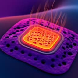
- Cell architecture and components: A zero-gap capillary-fed cell used an 8 µm PES separator (~140 µm thick, ~80% porous). Bipolar plate and gas diffusion layer were combined into perforated Ni plates that served as current collectors and gas outlets. Electrodes were pressed against the separator inside sealed gas chambers. The bottom of the separator was dipped into an electrolyte reservoir of 27 wt% KOH to maintain capillary feed.
- Electrocatalysts: OER anode: Ni mesh electrocoated with NiFe oxyhydroxide; some anodes incorporated a PTFE dispersion in the plating bath to modify microstructure and porosity. Anodes were spot-welded to their Ni bipolar plates to prevent contact resistance growth. HER cathode: 0.5 mg cm−2 Pt on carbon (Sigracet 22BB), prepared by airbrushing a Pt/C-Nafion ink; the cathode was compressed against the bipolar plate (contact resistance 3–5 mΩ cm²). No carbon was used at the anode to avoid oxidative corrosion artifacts.
- Operating conditions and electrochemical testing: Electrolyte 27 wt% KOH; temperatures mainly 80 °C and 85 °C. Two-electrode measurements from bipolar plate to bipolar plate. Linear sweep voltammetry from ~1.2–1.4 V up to 1.5 A cm−2. Chronopotentiometry for noise analysis (bubble signature) with 20 s holds, analyzing last 10 s standard deviation. Galvanostatic EIS at 0.35 A cm−2 (100 kHz to 100 mHz) to estimate series resistance. Controls: flooded, bubbled zero-gap cells with identical catalysts and 27 wt% KOH using (i) Zirfon PERL UTP 500 and (ii) PES separators; assessment of effect of anode welding vs compression contact.
- Faradaic efficiency and crossover: Gas evolution volumes for H2 and O2 were measured at 0.35 A cm−2 using inverted burettes after 30 min steady operation; expected volumes computed including water vapor and measured crossover. Hydrogen crossover into the anode O2 stream was quantified at room temperature across 0.1–1.0 A cm−2 via GC (TCD/FID, Ar carrier), compared to a diffusion-only model based on literature solubilities and diffusion coefficients in concentrated KOH.
- Balance-of-plant analysis: Conceptual comparison of conventional electrolyser BoP versus a CFE-based stack, highlighting elimination of liquid circulation loops, gas-liquid separators, large pumps/piping, and potential for air or radiative cooling due to higher efficiency; estimation of reduced water inventory (~500 L per MW vs ~10,000 L per MW).
- Capillary transport capacity: PES (8 µm) provided the highest in-plane capillary flow. Model and measurement indicate sustainable water delivery for electrolysis at 0.5 A cm−2 up to ~15 cm at room temperature and at 1.0 A cm−2 up to ~18 cm at ≥80 °C.
- Separator ionic resistance: PES (8 µm) with 27 wt% KOH exhibited 46 mΩ cm² at room temperature, substantially lower than Zirfon PERL UTP 500 (290 mΩ cm²) and lower than Nafion 115 (142 mΩ cm²) and Nafion 117 (220 mΩ cm²). The low resistance contributed to improved efficiency.
- Cell performance vs controls (80 °C):
- Bubbled control with Zirfon required 1.86 V at 1.0 A cm−2.
- Bubbled control with PES required 1.74 V at 1.0 A cm−2 (−0.12 V, ~120 mΩ cm² attributed to lower separator ionic resistance).
- Bubbled control with PES and welded anode required 1.66 V at 1.0 A cm−2 (additional −0.08 V, ~80 mΩ cm² by eliminating contact resistance).
- Capillary-fed cell (PES) without PTFE required 1.62 V at 1.0 A cm−2 (further −0.04 V, ~40 mΩ cm² attributed to largely bubble-free operation and architecture).
- Capillary-fed cell with PTFE at anode required 1.59 V at 1.0 A cm−2 (additional −0.03 V, ~30 mΩ cm², likely from increased ECSA and facilitated gas removal). Cumulative reduction vs bubbled Zirfon baseline: ~270 mΩ cm² at 80 °C.
- Commercial comparison (85–90 °C): CFE cell at 85 °C achieved:
- 0.294 A cm−2 at 1.470 V (100% HHV efficiency).
- 0.500 A cm−2 at 1.506 V (98% HHV), energy consumption 40.4 kWh/kg H2 (3.64 kWh/Nm³), surpassing IRENA 2050 target (<42 kWh/kg).
- 0.800 A cm−2 at 1.551 V (95% HHV); 1.000 A cm−2 at 1.575 V (93% HHV). Commercial alkaline and PEM stacks at ~90 °C required ~1.77 V to reach typical operating current densities (~0.5 and ~1.8 A cm−2, respectively; ~83% HHV, ~47.5 kWh/kg H2).
- Bubble-free operation evidence: Chronopotentiometry voltage noise standard deviation at 0.2 A cm−2 was 1.03 mV for bubbled control vs 0.14 mV for CFE; across 0.01–1.0 A cm−2, CFE remained largely bubble-free up to 0.2 A cm−2 and substantially bubble-free up to 1.0 A cm−2.
- PTFE effects: Incorporation of PTFE into the anode increased double-layer capacitance from ~0.46 to ~5.50 mF cm−2 (~12×), indicating higher ECSA; PTFE’s aerophilicity likely facilitated dissolved gas transport to the gas phase, mitigating bubble formation.
- Faradaic efficiency and gas crossover: Overall Faradaic efficiency 99.5 ± 1.3% at 0.35 A cm−2. Hydrogen crossover into the O2 stream was 0.04–0.14 vol% over 0.1–1.0 A cm−2 at room temperature, consistent with diffusion-only predictions up to ~0.2 A cm−2 and only modestly increasing thereafter. Oxygen impurity in H2 was below 0.001 vol% detection limit.
- Stability: Demonstrated stable operation for 1 day (80 °C) and 30 days (room temperature) with periodic reservoir water replenishment; no KOH buildup or crystallization observed in separator.
- Balance-of-plant implications: CFE eliminates needs for electrolyte circulation pumps, gas-liquid separators, and water-cooled chillers (air or radiative cooling feasible), reduces water inventory (~500 L/MW vs ~10,000 L/MW), and avoids shunt currents along liquid return lines, indicating potential CAPEX and OPEX reductions beyond stack efficiency gains.
The results validate the central hypothesis that capillary-fed electrolyte delivery enabling direct gas production and bubble-free operation can significantly reduce cell overpotentials and resistance compared with conventional flooded, bubbled systems. By removing bubble masking and counterflow multiphase transport, improving separator ionic conductivity, and ensuring robust electrical contacts (welding), the CFE cell achieves lower onset potentials and higher energy efficiency across practical current densities. The architecture also constrains gas crossover to diffusion in a concentrated alkaline medium, maintaining low impurity levels. Compared to commercial alkaline and PEM cells, the CFE’s lower voltage at equivalent currents translates into 15% lower cell energy consumption (40.4 vs ~47.5 kWh/kg), directly lowering the levelised cost of hydrogen. Furthermore, the simplified balance-of-plant—no large electrolyte loops, separators, or chillers—promises additional reductions in power consumption and capital complexity. Collectively, these advances push renewable hydrogen closer to competitiveness with fossil-derived hydrogen and offer a pathway to meeting or exceeding long-term efficiency targets.
The study introduces and demonstrates a capillary-fed electrolysis cell that supplies electrolyte via a porous separator to achieve largely bubble-free operation, coupled with low-resistance components and robust contacts. The cell attains 1.506 V at 0.5 A cm−2 and 85 °C (98% HHV, 40.4 kWh/kg H2) and maintains 100% HHV efficiency at ~0.3 A cm−2, outperforming state-of-the-art commercial alkaline and PEM cells. Faradaic efficiency approaches 100%, with very low gas crossover. The architecture further enables significant simplifications of the balance-of-plant, indicating potential reductions in both OPEX and CAPEX. Potential future work includes: scaling to multi-cell stacks and higher active areas; operating at elevated pressures; optimizing separator materials and geometries to extend capillary height or reconfiguring reservoir placement to eliminate gravity constraints; long-term durability and degradation studies under industrial duty cycles; catalyst cost reduction and stability (e.g., non-Pt HER catalysts); deeper quantification of the contributions to resistance and bubble suppression; and integration with renewable power systems to validate full system energy savings.
- The demonstrated system is a lab-scale single-cell with small geometric area; industrial scalability and manufacturability remain to be proven.
- Capillary-driven supply imposes a height limit (~15 cm at room temperature for 0.5 A cm−2; ~18 cm at ≥80 °C for 1.0 A cm−2) due to gravity; while mitigable by reservoir placement (top feed), this was not tested here.
- Performance and crossover were often characterized at room temperature or 80–85 °C and at atmospheric pressure; behavior under differential pressures and at higher pressures typical of industrial operation requires validation.
- Gas crossover and Faradaic efficiency were measured over limited durations; long-term stability (thousands of hours) and degradation mechanisms need comprehensive study.
- Contact resistance mitigation required welding of the anode; some commercial systems rely on compression contacts, which may reintroduce resistance growth if not addressed in design.
- The best-performing cathode used Pt/C; while common for benchmarking, non-precious alternatives would be needed for cost minimization.
- Absolute contributions of individual mechanisms (bubble suppression, ECSA increase with PTFE, architecture) to the net resistance reduction could not be fully deconvoluted.
Related Publications
Explore these studies to deepen your understanding of the subject.